Contactor introduction Contactors are divided into AC contactors (voltage AC) and DC contactors (voltage DC), which are used in power, distribution and power applications. The contactor refers broadly to an electrical appliance that uses a current flowing through a coil to generate a magnetic field in an industrial power to close the contacts to achieve a controlled load.
In electrical engineering, because it can quickly cut off the AC and DC main circuits and devices that can be frequently switched on with high current control (up to 800A), it is often used as a control object for motors, as well as for controlling plant equipment. The electric load of the electric heater, the working machine and various power units, the contactor can not only turn on and off the circuit, but also has a low voltage release protection. The contactor has a large control capacity and is suitable for frequent operation and remote control. It is one of the important components in the automatic control system.
In industrial electrical, there are many types of contactors, and the working current ranges from 5A to 1000A, and its use is quite extensive.
Contactor working principle The working principle of the contactor is: when the contactor coil is energized, the coil current generates a magnetic field, and the generated magnetic field causes the static iron core to generate electromagnetic attraction to attract the moving iron core, and drives the AC Contactor to act, and the normally closed contact is disconnected. The normally open contacts are closed and the two are linked. When the coil is de-energized, the electromagnetic attraction disappears and the armature is released under the action of the release spring, the contact is restored, the normally open contact is opened, and the normally closed contact is closed. The working principle of the DC contactor is somewhat similar to the principle of the temperature switch.
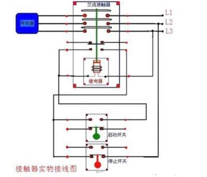
AC contactor wiring method 1, 3, 5 connected to three-phase power supply, (main circuit part)
2, 4, 6 connected to three-phase motor
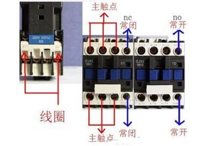
A1 and A2 are the coils of this contactor, which are connected to the control circuit to control the motor of the circuit part (with small control) by controlling the coil (A1, A2) of the contactor.
13, 14 indicates the auxiliary contact of the contactor, NO indicates that it is normally open, that is, 13 and 14 are disconnected when no power is applied, and 13 and 14 are closed after energization. Placed in the control circuit part with the lock (parallel on the start button) to achieve continuous operation.
First, the three phases of the power supply are respectively connected to the main contacts L1, L2, L3 of the contactor, and then the three terminals of the three wire-connected motors are connected from the T1, T2, and T3 of the contactor, and the above is the main circuit.
Control circuit: pull out a line stop button from L1 (the stop button is normally closed, the start button is normally open, this should be known!) From the stop button, one end of the start button and one end of the contactor auxiliary contact are connected. Then connect the other end of the auxiliary contact from the other end of the start button (this part is self-locking), the wire coming out from this end is connected to the coil A1, and the coil A2 is connected to the line L2 or L3.
First of all, we first understand the basic knowledge of Schneider AC contactor. There are two basic things in the AC contactor. The main contact and the auxiliary output are the main contacts. The main contact is used to contact the electrical device or connect to the main circuit. The auxiliary contact is connected to the control loop to control the main circuit.
The main contact is generally connected to the main circuit. As for the sequential order, there is no special requirement. The auxiliary contact is connected to the control loop. Generally, it is usually a normally open contact or a normally closed contact. This choice is based on the requirements of the control loop. Generally, an AC contactor is not enough if the normally open normally closed contact is used. For Schneider, for example, a mechanism can be added at the top. Similar to normally open normally closed contacts are available.
The AC contactor is judged to be normally open and normally closed. The universal meter can be used for the on/off range. When the universal meter is calibrated, it is a normally closed contact. When the universal meter is not sounding, it is a normally open contact. The button will open normally and will not ring normally.
220v contactor physical wiring diagram as follows:
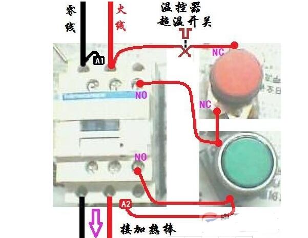
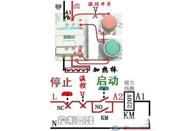
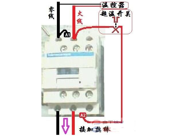
The thermostat power supply is directly 220 volts, and the normally closed contact [over temperature open contact] is connected in series to the control loop. In the other figure, NO is normally open and NC is normally closed.
supplement:
If the switch is not connected to the switch and the temperature controller is used for direct control, the power supply zero line is connected to A1, and the hot line is connected to the A2 by the over temperature disconnecting contact of the temperature controller [normally closed], so that the power can be heated and set. When the temperature reaches the temperature controller, the power of the magnetic coil is disconnected, and the AC contactor cuts off the power of the heating rod. A1 and A2 are the terminals of the magnetic contact of the AC contactor.
Contactor wiring port诀 The contactor assisted normally open contact is connected in parallel with the start button, and the combined body after the parallel connection is connected between the stop button and the contactor coil.
 Inquiry Basket (


 Scan to visit


